DREAM.3D Data Structure
Overview
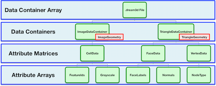
DREAM.3D uses an abstract, hierarchical data structure that has roots in the concepts of combinatorial topology and common methods for describing mesh structures. The generalized data structure follows a tree structure with the following possible node types:
- Data Container Array: The root node of the data structure. In most cases, a particular workflow will only have one Data Container Array, but this is not a hard requirement. The Data Container Array has access to create and retrieve all objects that descend from it, not just its immediate Data Container children.
- Data Container: Holds Attribute Matrices for data that belong to unique geometries. Two Data Containers are distinguised by their associated Geometry.
- Attribute Matrix: Holds Attribute Arrays, which are the containers for raw data. The type of Attribute Matrix labels the hierarchy level to which its associated Attribute Arrays corresponds.
- Attribute Array: Holds raw data in memory. DREAM.3D utilizes a flat data storage approach, such that even multidimensional data is allocated into a contiguous section of memory. This approach enables faster and more efficient compute times.
The above node types are commonly referred to as objects, while the data stored within them is referred to as the attributes of those objects. For most DREAM.3D functions, the user is given control over how to name the various objects within the data hierarchy.
Geometry
A special kind of object is known as the Geometry, which defines the spatial organization of the data. The Data Container objects are responsible for holding Geometries. In general, this means that the distinguishing characteristic between two Data Containers is their associated Geometry objects. Geometries are generally classified by the topology of their unit Element, which is the smallest building block of the geometry. Elements can have 4 different dimensionalities: 0 (points), 1 (lines), 2 (polygons), and 3 (polyhedra). In the DREAM.3D ontology, these are generally referred to as Vertices, Edges, Faces, and Cells.
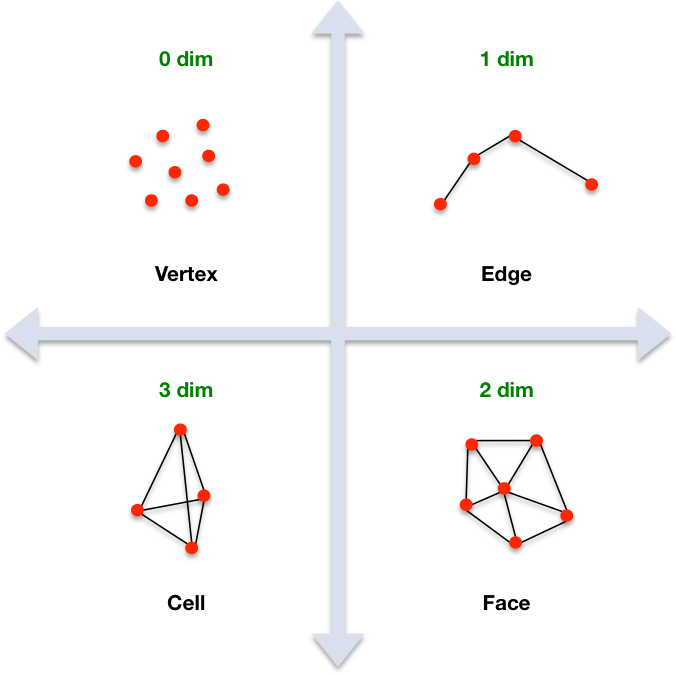
Data attributes can be associated with any of these element types, as long as that association makes sense for the given element topology. For example, a triangulated surface mesh can have Vertex, Edge, and Face data associated with it, but not Cell data, since a triangle has a 2-dimensional topology. To help the user keep track of the Geometry type associated with a particular Data Container, DREAM.3D sets default names of Data Containers to be prefixed with the Geometry type when applicable. For example, a Data Container containing an Image Geometry would have a default name ImageDataContainer. Of course, you can rename Data Containers if you prefer a different data scheme.
Currently Implemented Geometries
| Name | Topology | Associated Data | Description |
|---|---|---|---|
| Unknown | N/A | Any | A null geometry, used if the underlying data have no spatial layout |
| Vertex | 0 | Vertex | A collection of points, commonly referred to as a point cloud |
| Edge | 1 | Edge/Vertex | A collection of edges defined by two vertices, forming lines |
| Triangle | 2 | Face/Edge/Vertex | A collection of triangles; one type of surface mesh |
| Quad | 2 | Face/Edge/Vertex | A collection of quadrilaterals; one type of surface mesh |
| Image | 3 | Cell | A structured, rectilinear grid; this Geometry is composed of pixels (in 2D) or voxels (in 3D) with constant resolution |
| RectGrid | 3 | Cell | An unstructured, rectilinear grid; this Geometry is composed of pixels (in 2D) or voxels (in 3D) with variable resolution |
| Tetrahedral | 3 | Cell | A collection of tetrahedra; one type of volume mesh |
Attribute Matrices & Data Hierarchy
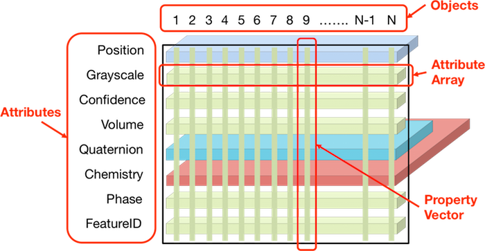
Data is organized in DREAM.3D using Attribute Matrix objects. These objects themselves do not store data; instead, they store the last level in the object hierarchy, called Attribute Arrays, which are the low-level containers for contiguous regions of data. There are a variety of different types of Attribute Matrices:
- Element: Attribute data associated directly with the features of the Geometry objects. Types of Element Attribute Matrices include:
- Vertex: Attribute data associated with vertices
- Edge: Attribute data associated with edges
- Face: Attribute data associated with polygons
- Cell: Attribute data associated with polyhedra
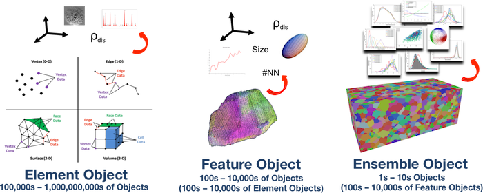
- Feature: Attribute data associated with collections of Elements
- Ensemble: Attribute data associated with collections of Features
The four different types of Element Attribute Matrix correspond to the four possible levels of dimensional topology for a given Geometry. For example, a Triangle Geometry may have a Vertex Attribute Matrix that stores an Attribute Array that defines a scalar at each vertex, and a Face Attribute Matrix that defines a vector on every triangle. This example points out one of the advantages of the DREAM.3D data structure: data with any amount of dimensionality can be stored efficiently thanks to the generic object-attribute associations. Note as well that the Attribute Matrix itself defines the tuple dimensions for a given kind of data, whereas the Attribute Arrays in that Attribute Matrix define the component dimensions of the raw data. For example, consider a Triangle Geometry with 20 triangles. A Face Attribute Matrix for this Geometry will have 20 tuples; i.e., the number of triangles. An associated scalar Attribute Array in this Face Attribute Matrix will also have a tuple length of 20, since 20 x 1 = 20. But an Attribute Array that defines a vector (such as a normal for each triangle) would have 3 components. This vector array is still associated with the triangles, so it is stored in the Face Attribute Matrix. The total number of tuples for the underlying array in this case is now 60, since 20 x 3 = 60.
A given Data Container should only have at most one type of each of the different varieties of Element Attribute Matrix. This arises because a given Geometry should only have one way to organize its unit elements in space (e.g., the number of triangles in a Triangle Geometry remains fixed). If the number of any of the components of a Geometry change, then that defines a new Geometry that should belong in a new Data Container with new associated Attribute Matrices. Note that if the elements of a Geometry merely move (e.g., via a mesh smoothing process), then there is no need to instantiate new Attribute Matrices, since the underlying tuple dimensions have remained constant.
The underlying Elements of a given Geometry can be grouped together to form collections of Elements via some classification rule. A common example is segmenting a grayscale image by assigning all pixels with less than a certain grayscale value to class 1, and all others to class 2. This procedure introduces a sense of hierarchy to a data stream. DREAM.3D refers to these collections of Elements as Features. These Features can then have data associated with them through a Feature Attribute Matrix. Any kind of Element may be grouped into Features, and there may be many different ways to group said Elements. Therefore, Data Containers can generally contain as many Feature Attribute Matrices as are necessary. To continue the hierarchy scale, DREAM.3D allows for Features to be grouped together to form Ensembles. Again, these Ensembles can have associated Ensemble Attribute Matrices to store data, and there may be many Ensemble Attribute Matrices in a given Data Container. In principal, it is even possible to have Ensembles of Ensembles! In this manner, the DREAM.3D data structure allows data associations to bridge across mutiple length scales.
Both Features and Ensembles must be made up of some specific Element type at the lowest level. DREAM.3D currently requires that any set of Features (and thus Ensembles as well) must be composed of the same unit Element type. For example, Features can be made up of a collection of Triangles, but not both Edges and Triangles. Of course, it is possible to have a set of Features made up of Edges only and a set of Features made up of Triangles only within the same Triangle Geometry. To help the user keep track of these distinctions, DREAM.3D names Feature/Ensemble Attribute Matrices with a prefix that identifies the unit Element building block by default. For example, a set of Features made up of Cells would have a default Attribute Matrix name of CellFeatureData. Of course, you can rename Attribute Matrices if you prefer a different data scheme.
A key concept behind Features and Ensembles is the existence of a map that ties the entries in a Feature/Ensemble Attribute Matrix to one level lower in the hierarchy. The values in this map are commonly referred to as Ids. For example, consider an Image Geometry in 2D that has a set of 10 Features within it, defined by 10 groups of pixels. The Attribute Matrix associated with this set of Features will have 11 tuples. Why 11 and not 10? DREAM.3D begins numbering Features and Ensembles at 1, and reserves the 0 value for special use. Therefore, the number of tuples for a given Feature/Ensemble Attribute Matrix is always one larger than the actual number of Features/Ensembles. Since the Features are groups of pixels (a kind of Element), DREAM.3D associates each pixel with a particular Feature. These Feature Id values correspond to integers that sit on the pixel Elements, and allow DREAM.3D to index into the Feature Attribute Matrix by knowing the Feature Id at one level lower in the hierarchy. The same concept applies to Ensemble Ids sitting at the Feature level. These map associations enable DREAM.3D to efficiently link between the various hiearchy scales, allowing for connections and correlations to be assessed.
For a detailed discussion of the DREAM.3D data structure and its associated applications to the analysis of microstructure data, please consult this IMMI paper.
Filters, Pipelines & Plugins
Manipulation of the underlying data structure is exposed to the user through the use of Filters. A Filter can be considered a self-contained function, which takes the existing data structure as input and performs some series of operations to modify the data structure and produce and output. Filters can be strung together to form a Pipeline, in which the data structure flows through the set of Filters, being modified along the way. If a Filter reads in data from outside of DREAM.3D, then the new data will be incorporated into the existing data structure. Or, if no data structure yet exists (e.g, starting from a "blank slate"), a new one will be created. More information on creating Pipelines can be found in the Using DREAM.3D section.
Filters in DREAM.3D are contained within Plugins, which are collections of Filters with similar scope. The Plugin itself is the actual library into which the Filters are compiled. The Filters' locations within the interface is determined by their group and subgroup labels, and may not correspond to their actual Plugin library. This discrepancy is done to better organize the interface by sorting Filters by their general functionality. For example, a developer may write a Plugin for analyzing output from a simulation, and have a Filter that performs the import of the simulation data into DREAM.3D. This Filter will be compiled into the external Plugin, but it may be wise for the developer to place the Filter in the IO group and Input subgroup, since the Filter's functionality is to import data. Note that the Filter Documentation section organizes Filters by Plugin, not by their group.