Creating a Pipeline
In DREAM.3D, the user processes their data by creating what is known as a Pipeline which is constructed out of a series of Filters. By chaining together a series of Filters, the underlying data structure is processed and modified in quick succession. The user should be aware that all processing on the data is done in place, i.e., there is only a single copy of the data resident in memory at any one time. While this reduces the overall memory footprint, the user will have to be aware that their data may be modified from its original form. To help the user avoid accidentally overwriting data, all objects at a given hierarchy level in the data structure are not allowed to share the same name. For example, a data structure can have an Attribute Matrix named foo that holds an Attribute Array named bar, but if the user tries to create a new Attribute Matrix named foo, an error will be presented in the Pipeline Error Table. The user is allowed to create another Attribute Array named bar, however, as long as that Attribute Array belongs to a different Attribute Matrix. In other words, no two children of a given data structure object can share the same name!
Building a Pipeline
The interface mechanics of building a Pipeline are discussed in the Overview of the User Interface section. The concepts behind creating a Pipeline are presented here. In an abstract sense, a Pipeline can be thought of as a series of tubes, where the individial pieces of pipe are the Filters. The fluid traversing the Pipeline is the underlying data structure. The Filters can change the overall direction of the data structure, compress it, morph it, modify it, and add to it, until finally the data structure comes out the other side. Each individual Filter will require certain kinds of inputs, which means that some Filter further up in the Pipeline must, at some point, create those necessary pieces of the data structure. DREAM.3D alerts the user if any of these pieces are missing by executing a process called Preflight. Think of Preflight as compiling a computer program: any compiler errors are populated in the Pipeline Error Table. Using this feedback, a user can modify the parameters of existing Filters and add new Filters to the Pipeline until all errors are silenced. It is then safe to run the Pipeline by clicking Go! While the Pipeline is running, you can click on Filters in the Pipeline View and inspect the items in the Filter Input View. Also, the Start Pipeline button will change to a Cancel Pipeline button when a Pipeline is running. Clicking Cancel Pipeline will stop the Pipeline execution. Note that some Filters may not check for this Cancel Pipeline click at any point during their operation. If this is the case, the Pipeline may wait to quit until after the current Filter has finished running.
But how do you know what kind of Pipeline to create? What are the primary ingredients of a useful Pipeline? First, it is important to become familiar with the DREAM.3D ontology. The best place to start is by reading and understanding the DREAM.3D Data Structure section. The terms presented to the user on Filters will use the same language as explained in the DREAM.3D Data Structure section. Once you are familiar with the DREAM.3D language, understanding the functions of Filters becomes much easier. The Filter Documentation is also useful for getting to know specific Filters.
When constructing a Pipeline, try to think about your data in terms of the DREAM.3D language. What kind of Geometry are you working? Is it a 2D picture made up of pixels (an Image Geometry)? A triangulated surface mesh (a Triangle Geometry)? What are the unit elements of your Geometry? More importantly, where on your Geometry does your data lie? The dimensional topology of the Elements the data lie on determines the type of Attribute Matrix to which that data will ultimately belong. For example, a 3D stack of images with grayscale data at every voxel would have a grayscale Attribute Array located in a Cell Attribute Matrix.
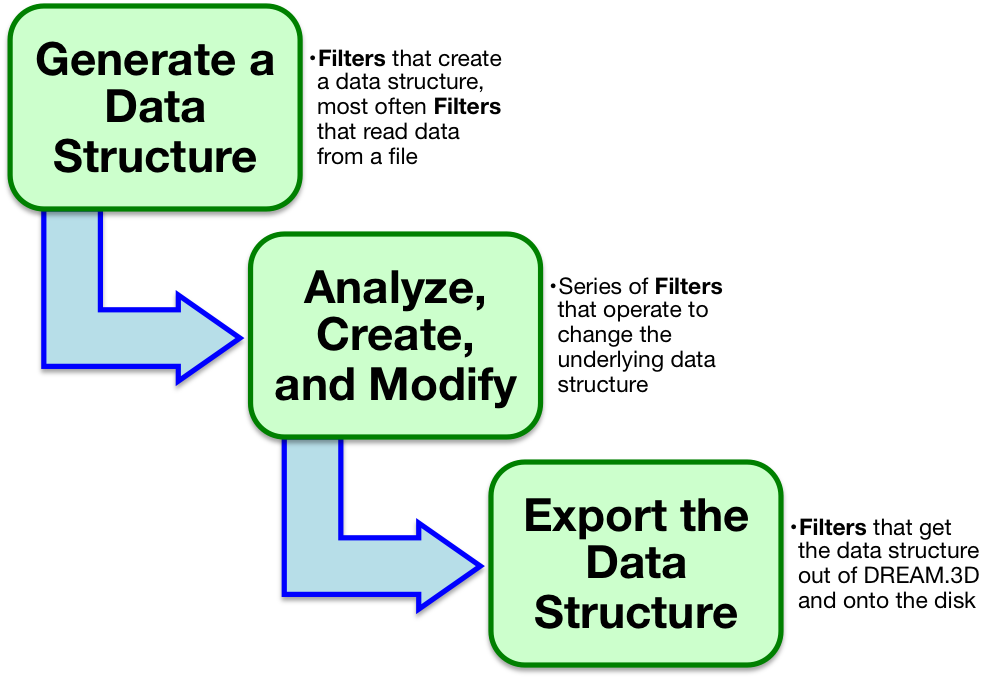
Once you've translated your data into the DREAM.3D ontology, you can start thinking about constructing a Pipeline to do something interesting. All Pipelines will need to start by creating an instance of the DREAM.3D data structure in some fashion. This is usually accomplished by reading in some data from a file. Visit the Supported File Formats section for information on the kinds of files DREAM.3D can understand. Next, you'll want to string together Filters to accomplish an analysis. This is the interesting part about building a Pipeline. You can begin anlayzing the underlying data that lies on your Geometry, or think about grouping Geometry elements to form Features. For example, in the 3D grayscale image stack example, you may wish to group all elements into two classes by applying a threshold. This would group the Geometry elements into 2 Features. There are a host of Filters used to analyze your newly created Features, calculating information like their sizes and shapes (and much more!). At all steps in creating a Pipeline, try to think about your data using the abstract DREAM.3D ontology. This will not only help you in understanding what Filters do, but also allow you to remain flexible. Be imaginative!
After you've constructed the analysis portion of a Pipeline, you'll probably want to export your new data structure to your disk. Again, the Supported File Formats section explains what sorts of files you can export. In particular, the native .dream3d file format is very useful, since it was designed to handle the abstract data structure. Also, the file is based on open source HDF5, meaning anyone can read the data!
Over time, you'll probably want to start saving your Pipelines so you can streamline the Pipeline creation process or share your workflow. The Saving & Opening Pipelines section gives more details on this process.